prototyping the light Cube:
An introduction to Arduino
What is an Arduino?
It is a development platform that will help you prototype an interactive object. Huh...that’s a loaded sentence, let me break that up for you:
With the Arduino, you can easily create whatever interactive device your heart desires. All you need to do is first setup the hardware. Hookup some sensors (input) into the Arduino in order for it to sense the world around it in some way (light detection, temperature sensing, etc.). Then hookup some actuators (output), like a motor or an LED, to respond to the thing it is sensing. After you setup your hardware, you hookup your Arduino to your computer via a USB, load up the Arduino app, and code up the Arduino to behave the way you want it to using the sensors and actuators that you hooked it up to.
Now that you know what to aim for when dealing with an Arduino. Lets actually get there (wherever it might be, which, if you are a true Arduino developer, you don’t know), by diving into the nitty gritty details of electronics and programming.
1: Setting Up
Go to http://arduino.cc/en/Main/Software and download the Arduino software for your respective operating system.
Follow the instructions on this page for your respective operating system: http://arduino.cc/en/Guide/HomePage, it will show you how to install the Arduino
and load up a sketch called Blink. Now a sketch is the software you’ll upload into the Arduino to make it behave like a desired device. The Blink example sketch will simply turn the Arduino into a device that blinks its onboard LED.
2: Hooking up to the arduino
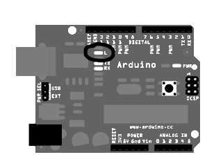
From the last step, you should have the Blink example loaded up to your Arduino. To make sure this is so, the onboard LED should be blinking.
The onboard LED is the one circled, with the ‘L’ next to it.
Now let us take matters into our own hands and make one of our LEDs blink.
First, let us get accustomed to the breadboard. In the same way that artists paint on canvas, Makers setup circuits on a breadboard. The breadboard is composed of holes that you place the wire endings of your electrical components into. Each row of 5 holes are a single wire and they help you connect together different electrical components such as LEDs or resistors.
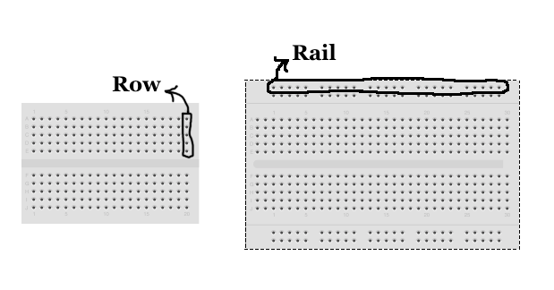
Whatever is plugged into the rows or rails on a breadboard are wired up. Notice how the breadboard on the left is just the middle of the larger breadboard on the right.
Don’t worry so much about the details. Just follow the diagrams, ask for help when you’re confused, and you (and the electrical components) should be fine.
UNPLUG YOUR ARDUINO BEFORE CHANGING CIRCUITS!
Now setup your circuit to make it match this diagram (the 33o Ohm resistor is the one with the orange, orange, brown color bands on it):
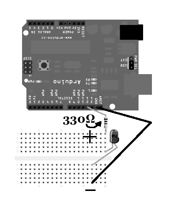
Plug your Arduino back into the USB board and the LED should blink. If it doesn’t, you might need to spin your LED 180° in order to switch the wiring.
Okay, it works, but what’s going on? Look at the Blink example code and notice “digitalWrite.” Also notice the number ‘13’ within the parenthesis and the word “HIGH.” Also notice that your LED is hooked up to a pin labeled number 13. What you are programming the Arduino to do is send 5 volts (HIGH) out of pin 13. This action powers the LED and turns it on.
Pin 13 is part of a row of pins known as the Digital Input/Output pin. You set these pins to either take in or output digital currents (electrical currents that simply go on and off). Right now, for this tutorial, you are only using these digital pins to output 5 volts of electrical current.
Don’t worry about digital input, for the next step we’ll try to sense the real world, which, unfortunately, is analog and therefore we’ll be using the Analog input.
3: creating Light cube
See that row of pins labeled “Analog In?”
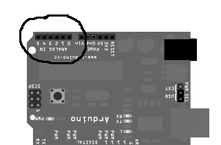
Each pin takes in electrical current that ranges from 0 volts to 5 volts. Arduino transforms the voltage it reads from that range and converts it to an numerical value between 0 and 1023. Using the value from this input, you can interact with the real world because you know what is going on outside your circuit.
But with what exactly? Well there are a lot of electrical components that you can use that causes a change within that 0-5 voltage. This change is induced when real world events enacts upon these special electrical components. These components are called sensors.
The sensor we’ll be using for our input is the photoresistor, but we’ll call it a light sensor. The way it works is this: the more light that strikes upon the light sensor, the more voltage it allows into the analog input until it reaches a maximum voltage of 5 volts. Lets hook it up!
UNPLUG YOUR ARDUINO BEFORE CHANGING CIRCUITS!
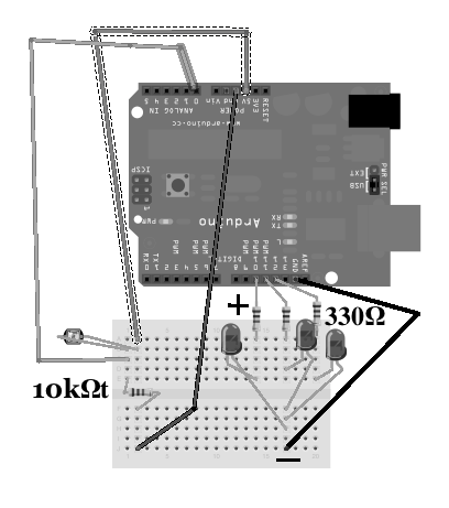
Now setup your circuits to make it match this diagram (the 10k Ohm resistor is the one with the brown, black, orange color bands on it and the 33o Ohm resistor is the one with the orange, orange, brown color bands on it):
Plug your Arduino back into your computer, create a new sketch in your Arduino app called ‘ColorChangePerSwipe,’ go to http://www.datspace.net/introToArduino/code , click the link “Download Raw,” copy and paste the code, press the play button, and finally press the arrow icon ![]() that is pointing to the right
that is pointing to the right ![]() . If all is wired up correctly, your three LEDs should alternate everytime a shadow passes over the light sensor.
. If all is wired up correctly, your three LEDs should alternate everytime a shadow passes over the light sensor.
Yet all we’re seeing is LEDs turning on or off. Boring. Let us put a paper cube over the three LEDs to diffuse and mix the colors.
Cut a hold on one face of the paper cube cutout. Fold, tape it, and line the insides with tissue. Carefully place this over the LEDs (and not the light sensor for obvious reasons) without jiggling the wiring (breadboard isn’t exactly a stable connection of wires). Presto! You have a light cube ◕▿◕
One last thing to notice about your code: setup() and loop(). The way Arduino behaves is like this. First it executes the instructions in setup() once. Then it executes the instructions in loop() repeatedly. As the name implies, Arduino loops through each instruction, one by one, forever. The reason? The real world never ends (theoretically) and so the Arduino always needs to check up on it.
Final step: Hack up something new
The Arduino was created to allow you to tinker with ease. Mess around with you’re newly created circuit. Here are some ideas: find a better way to detect a hand wave using the light sensor, control your computer instead of the LEDs (or both) http://is.gd/6Q46Wz , use the PWM pins to fade the LEDs and get more ranges of color, or do something completely unexpected.
References